Understanding Hybrid-Filter Transmitter Combiners
By: William F. Lieske, Sr.Founder, EMR Corporation
Download PDF
Table of Contents
Introduction
More than forty years ago devices known as hybrid couplers were used to couple signal paths to a common source or load. One of the more important applications is in transmitter combiners. With the use of power handling hybrid couplers, along with ferrite isolators, filters and load terminations, many transmitters may be coupled together to a common antenna.
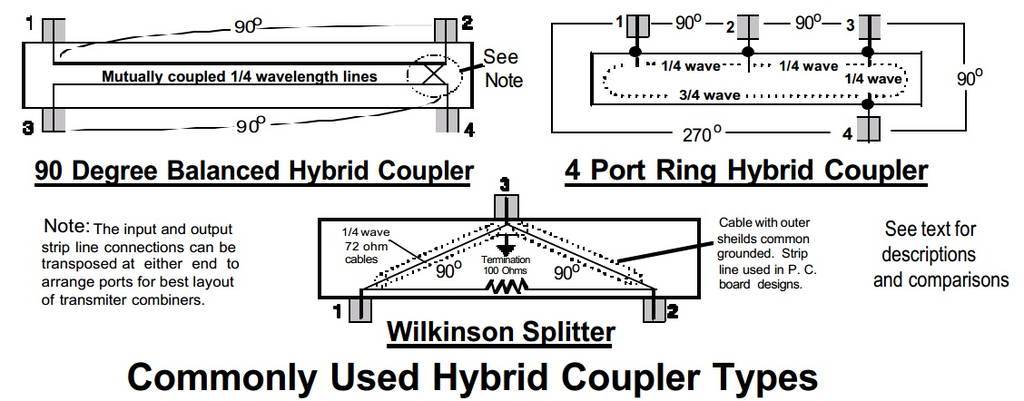
Figure 1
The Hybrid Coupler
There are several types of hybrid couplers. Those found in today’s wireless land mobile systems include:
- 90° mutually coupled line type.
- Wilkinson Splitter type.
- Ring or loop type hybrid.
Figure 1 shows the various hybrid coupler types schematically. The 90° Balanced Hybrid Coupler consists of two 50 W strip lines arranged to be mutually coupled. The strip lines are made in various ways including PC board traces, copper or brass strips placed between high dielectric insulation materials.
A signal applied to the Port 1 & 2 line will be coupled to Ports 3 & 4. Since the lines are electrically ¼ wavelength long the currents and voltages are changed in phase between Ports 1 & 2 and Ports 3 & 4. Forward loss is 3 dB plus incidental conducted losses.
Note that this places Ports 1 & 3 and Ports 2 & 4 at 180° in phase relationship. If a signal is applied to port 1 and Port 4 is terminated with a 50 W load termination the applied power will be equally split between Ports 2 & 3. Conversely, power applied to Ports 2 & 3 will be split between Port 1 and the termination at Port 4. With this device two transmitters can be coupled to a common antenna. All impedances will be matched and a high order of isolation is provided between the transmitter P.A. circuits, at least 30 dB for the hybrid coupler alone.
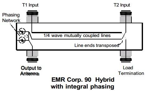 Figure 2
The strip lines are transposed at one end to facilitate the best chassis layout for a Hybrid –Ferrite transmitter combiner. Note that the T1 and T2 input connectors are on the same side of the hybrid housing. We have also included a network at the antenna port that when properly adjusted, will produce more than 65dB of isolation between the T1 and T2 input ports.The Wilkinson Splitter employs two 70 W sections of line, each ¼ wave length. Each line will produce a phase change of 90° resulting in a 180° phase relationship between Ports 1 and 2. The 100 W terminating resistor provides an effective match at the isolated ports and the conjunctive impedance of the two 70 W lines in parallel is 50 W at Port 1.
Wilkinson Splitters are mostly used for dividing signal power to feed a number of devices from one source. One example (Figure 3) is an 8-way signal power divider for receiver multicoupling service. Of course, it works in reverse, to combine low power transmitters, provided that the 100 W termination resistors and related heat sinks are capable of dissipating ½ of all power applied to the inputs. Insertion loss is 3 dB plus conducted circuit losses and isolation is usually 25 dB or better between ports.
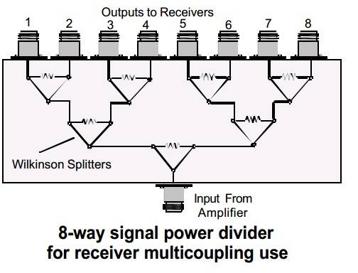 Figure 3
The Ring Hybrid can be made with cables or strip lines. For frequencies below about 200 MHz, however, the loops of cable are clumsy to mount and performance tends to change over time due to characteristic changes of the dielectric materials of the cable. The ring hybrid is well suited for manufacture from 400 MHz to more than 2 GHz as physical dimensions become manageable throughout these ranges.
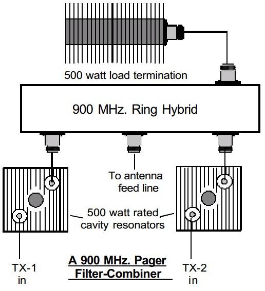 Figure 4
Figure 4 shows an example using the ring hybrid coupler. This is a combiner for two 930 MHz Band 500 watt paging transmitters together with additional filtering provided by the series band pass cavity resonators. It is a good example of how hybrid couplers and filter components blend together to meet needed system performances in terms of transmitter combining with I.M. interference control.
Hybrid – Ferrite Combining Designs
Most hybrid coupled combiners are supplied with dual junction ferrite isolators to prevent the combined transmitter signals from mixing in power amplifier stages and producing I.M. products. Some transmitter manufacturers now incorporate a single junction isolator into their equipment design. Although this is done mostly as a protective measure to the high power amplifier output stage components, 20-25 dB of isolation is usually provided. Where potentials exist for I. M. products at a given site, additional single or dual isolators may be required as part of the combining system.
If you have read over our Bulletin: “The Care And Feeding of R. F. isolators”, the need for placing a 2nd harmonic or low pass filter at the isolator output is explained. Typical hybrid couplers provide only a small amount of harmonic rejection, so it is necessary to include harmonic or low pass filtering in any hybrid – ferrite design.
A Practical, Proven Design Example
Figure 5, below, is a drawing of an EMR Corporation Model 25522 Medium Power Transmitter Combiner for combining two closely spaced transmitters in the 450-470 MHz band. This combiner is rated to 125 watts continuous duty provided that sufficient free air flow is available to take heat away from the hybrid load termination through convection. Where rack or cabinet temperatures exceed +50 C. at least 75 C. F.M. of forced air must be directed toward the major components. A nominal site ambient temperature of 68° F. (+26° C.) will ensure that the combiner components will function normally even at high operating duty cycles. All hybrids must provide two 90° phase shifts, one positive and one negative in phase relative to a reference frequency. When this condition is met, two things occur: (1) The power of each input signal splits between the antenna and the load termination, and (2) the input ports are 180° apart in phase. The amount of isolation between them is determined by how well the system has been matched.
 Figure 5
This effect is demonstrated in Figure 6. There are two very closely spaced transmitter frequencies, 459.975 and 460.025 MHz to be combined. Note that we phase the hybrid on the mean frequency 460.000 MHz. The dark vertical lines represent the two transmit frequencies.
There is about 65 dB of isolation between the two transmitter input ports. In this case about 22 dB of isolation is provided at +/- 25 MHz from the center frequency. Also, the hybrid response will be as shown when it has been properly phased to place the rejection peak midway between the combined channel frequencies.
 Figure 6
In the real world, antenna and transmission line characteristics change almost constantly due to the effects of temperature, humidity and component degradation. The hybrid coupler stays put as tuned, resulting in the effective isolation being reduced as conditions change. Fortunately, there will be at least 30 dB of residual isolation under the extremes of this drifting. This, plus the 75 dB or more of isolation reverse signal rejection, will provide 100 dB or more of total isolation between the transmitters.The combiner portrayed in Figure 5 has several noteworthy features. First, it is quite compact, mounting in standard 19” relay rack or cabinet, rack space occupied is only 3-1/2” and capable of operating at 125 watts with 70% duty cycle. By adding heat sinks on the isolators and providing thermostatically controlled forced air cooling, 150 watts continuous power input can be applied.
4, 8 Or More Combined Transmitters
Looking at Figure 3, we see how a “tree” of seven Wilkinson splitters can combine eight transmitters to a common system antenna. Obviously, any type of hybrid will function, provided suitable power handling is present. For practical transmitter combining either the 90° or ring types are usually employed.
Combining with hybrid couplers is the only practical way to combine a number of frequencies that are very closely spaced from each other. By comparison, it becomes impractical to combine closely spaced channels using ferrite-filter designs since at some finite spacing the per-channel insertion loss of the filters exceed that of hybrid couplers. Conversely, hybrid combining widely spaced channels results in unnecessary system losses.
These considerations lead to making the most suitable choice of combiner type to be used for a particular application and frequency group.
Regarding Hybrid Combiner Power Loss
Earlier, we noted that each input signal is split between the output port and the hybrid’s load termination. Each hybrid split results in 3 dB of power loss plus as much as 0.30 dB of cable, connector and residual losses in the hybrid itself. In system design work we use 3.2 dB per split which turns out to be quite close in practice.
In addition, we must assign at least 0.50 dB for accumulated losses of the isolator, short jumper cables and 2nd harmonic filter for each path. This totals between 3.70 and 3.80 dB per channel loss in typical EMR Corp. two channel combining systems.
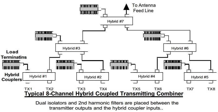 Figure 7
4-way combiners will have two hybrid splits at 3.3 dB each plus isolator and conducted losses for an average of 7.0 to 7.2 dB loss per path channel loss. For 8-ways, this goes from 10.3 to 10.5 dB per channel. With 100 watt transmitters, this results in 9.5 to 9.7 watts of power to the antenna feed line after losses in the combining process.
Only in special systems is this amount of loss acceptable. An example would be the now almost defunct IMTS radio systems, that used 11 VHF channels separated by 30 kHz each or 12 UHF channels separated by 25 kHz each. 250 watt transmitters were lined up at the site and up to 8-way hybrid-ferrite combiners were used to end up with 21 or 22 watts per channel to the antenna. On occasion two antennas were used, saving 3 dB, with two 4-way combiners. This saved half of the combined power and met needs where an E.R.P. of up to 80 watts could be used including the signal enhancement through the use of “gain” antennas.
As we near the turn of the century we find that multi-channel analog systems are now being combined at powers of a few watts and the combined outputs fed to linear power amplifiers. Digital systems, although their average power output is lower, transmit continuously, 24 hours a day. It must be acknowledged that such amplifiers are hard pressed to exhibit an intermodulation distortion (I. M. D.) characteristic equal to or better than 65 dB below the average combined carrier level. Cellular and land mobile sites alike tend to suffer new problems from I.M. interference for this reason.
Special Hybrid Combiner Systems
Channel frequencies are often random in both spacing and number leading to the need for combining three, five, six or seven close spaced channels. Where uniform combining power loss is desired this will determine that the next highest order hybrid arrangement is used. For example, for three channels we would use a four channel combiner, omitting the isolator and harmonic filter for channel four and terminating that hybrid input port with a 50 ohm termination.
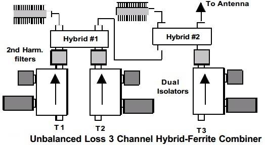 Figure 8
Where uniform per channel losses are not important, a two hybrid arrangement can be used as shown schematically in Figure 8.
Insertion loss for T1 and T2 paths will be 6.9 to 7.2 dB and the T3 path will be about 3.8 dB. Figure 9 shows the layout and rear view of a Hybrid Coupler Panel for combining with up to 125 watts per channel rated combiners. Along with optimized cable types and lengths the hybrid “tree” shown in Figure 7 can be assembled in a relay rack or cabinet.Panels of 7”, 8-1/4” and 10-1/2” height are used with larger load terminations of 150, 250 and 500 watt ratings. Larger scale and high power (up to 250 watts per channel input) combiners are rack or cabinet mounted to suit the customer needs.
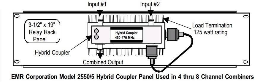 Figure 9
Ordering Hybrid-Ferrite Combiners
When ordering your combiner from the manufacturer or distributor provide the following:
- All channel frequencies to be combined,to the nearest kHz.
- Power output of all transmitters to be combined.
- Information about transmission line and antenna that you will be using.
- System duty cycle, worst case busy hour operation.
- Mounting: If in a cabinet, how much heat is to be moved by fan(s). A bit more than ½ the total input power will be converted to heat and must be exhausted to open air.
If you should select EMR Corporation equipment, we will mock up the combining system in our laboratory to verify performance prior to packing and shipping. Most manufacturers do this since real problems can develop if random type and lengths of cable are used for the jumpers or individual combiner modules are randomly cabled together.
We also assist our customers in the selection of the most optimum combining method. If preferences are expressed or special considerations must be met our experience will be used to assure you a satisfactory system.
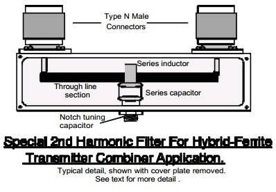
Figure 10
More About 2nd Harmonic Filters
A special model of a 2nd harmonic filter is depicted in Figure 10. In the illustration, Figure5, the components that connect the isolator outputs to the hybrid inputs are this type of device.
In this design, an almost perfect 50 W input and output impedance is secured along with a 2nd harmonic notch of 40 to 45 dB. Since this device replaces jumper cables and connectors the overall per channel insertion loss is reduced to nominally 0.05 dB or less.
On Pages 12 & 13 of our write up: “The Care And Feeding Of The R. F. Isolator” our standard 2nd harmonic filter and low pass filters are discussed. These are used in special low power hybrid coupled combiners and in high power (above 150 watts input) models.
Installing Hybrid – Ferrite Combiners
The instruction manual supplied with each combiner covers general installation recommendations and system adjustments. We offer the following Do’s and Don’t for your guidance:
- Don’t install a hybrid-ferrite combiner in a fully enclosed cabinet or a poorly vented cabinet along with other heat liberating devices such as power supplies and transmitter power amplifiers. Remember,more than ½ of the total input to the combiner must be converted to heat. This heat must be pushed out and conducted to the room air and replaced by suitable cooled air.
- All equipment, including the combiners will operate more efficiently and effectively when the site temperature is maintained between 65 and 70øF by full time air conditioning.
- Use only high quality connectors and inter-cabling from the transmitters to the combiner and from the combiner output to the main antenna feed line. Be sure that jumper cables are double shielded or solid copper shielded for stability and control of unwanted signal radiation.
- Try to arrange equipment to be combined such that the least amount of cable will be required. Try to locate the transmitter combiner (and its associated receiver multicoupler) in a central place with radio cabinets next to the combiner. This will minimize cable lengths which contributes to I.M. control. Be sure to leave access to the rear of combiner modules for initial and routine tune-up requirements. Be sure that a solid system ground is provided for the combiner(s).
Tuning Hybrid – Ferrite Combiners
At time of installation, it is necessary that the hybrid couplers are balanced to provide the highest possible isolation between combined transmitters. We also recommend that this procedure is conducted once every six months. The reason for this is that changes in the nature of feed lines and antennas occur through natural aging process such that the TX to TX isolation is reduced by 20 to 40 dB over that period of time.
To accomplish this, an accurate swept signal generator (can be your service monitor) and a spectrum analyzer with amplitude measurement capability of 80 dB or greater are needed. A tracking generator with a display or wave analyzer setup is the preferred instrumentation.
This tuning must be done with the system antenna and line in place as it will be during normal system operations. The procedure is really quite simple. Before undertaking this, however, you should qualify the antenna and line by using a portable watt meter with one transmitter and checking to see that the reflected power is less than 4% of forward power. (VSWR of 1.1:1).
- Referring to Figure 5, we see a dual isolator toward the right of the combiner chassis. Remove (unscrew) the larger output section load termination. Remove the TX #2 input cable and place the load on to the #2 isolator input port. This keeps the isolator in tune.
- Calculate the mean frequency of the two channels. Example: (T1)=152.240 MHz and T2=152.740 MHz are being combined. The mean frequency using the formula:
F “mean” = (T2 “highest” – T1 “lowest” + T1) / 2
will be 152.490 MHz. Set your signal source to that frequency and to the center of your analyzer display. - Set your analyzer for 10 dB per vertical division resolution. Connect your test cables together with a “bullet” adapter and adjust your instruments such that a full screen indication exists and your test frequency is at center screen, set display width to 20 MHz. (2 MHz per division).
- Plug the signal generator cable into the TX#1 input connector and the spectrum analyzer into the open load port of the TX #2 isolator.
- Remove the cap plugs from the hybrid.Using a small bladed screwdriver or tuning tool, carefully adjust the ceramic trimmers alternately for best isolation. If using a signal source with a spectrum analyzer, you will see the signal level decrease with each alternate adjustment.
- With swept signal equipment you will progress to a pattern similar to Figure 6. After several alternate adjustments, a notch of at least 60 dB will be secured if the antenna system has a VSWR of under about 1.2:1. It might be necessary to lengthen or shorten the combiner output jumper cable to the main transmission line by an approximate ¼ wavelength to find a suitable phase angle that can be met.
- When optimized, return the Isolator #2 load termination, re-connect the TX #1 input cable and replace the hole covers on the hybrid coupler.
If your system combines more than two channels, look again at Figure #7. With the system antenna in place, phase Hybrid #7 first driving its “T1” port and monitoring at its “T2” port and phase for best isolation. Re-connect cables to Hybrid #3 and Hybrid #6 output ports. Phase Hybrids #3 and #6, then re-connect their cables. Use the procedure given to phase the four two channel combiners.
Maintaining Hybrid-Ferrite Combiners
Visual inspections are generally all that you need to do, making sure that adequate air movement has not been blocked to the combiners. The hybrid load terminations will run hot, as they are supposed to do. Isolator output port termination heating is usually an indication of antenna, line or connector problems.
When at your site, very carefully touch each isolator load termination. If all is well, small heat rise might be noted. If hot to the touch, you can wager that there are antenna system problems to find and correct.
Unique Hybrid-Ferrite Combining Systems,Errata:
- Where isolation between transmitting and receiving antennas is limited, such as on short towers, it is possible to duplex groups of transmitting and receiving signals on a common antenna.
- Special duplexer designs must be used that will have sufficient bandwidth to pass the separate receive and transmit frequency groups and to provide sufficient reject characteristics over the bandwidths involved. In these cases, band pass cavity pairs are custom tuned and placed in line to supplement the performance of pass-reject duplexer types.
- Similarly, separate antennas may be used,augmented by band pass filters to secure needed transmitter wide band noise and carrier suppression.
- Where a group of transmit frequencies includes several close spaced channels(covering, say, 200-300 kHz overall) and another channel is spaced 1 MHz or more above or below this group, a combination of hybrid and filter coupling can be used effectively.
- Special power handling versions of the Wilkinson Splitter are constructed using special line impedance to derive 3, 5 and 7 way combining with a valuable saving in insertion loss. 3-way units check out at about 5 dB of loss, 5-way at under 7 dB of loss and 7-way at under 9 dB of loss. To make these perform properly, particularly at frequencies above 500 MHz, special low capacitance to ground power resistors must be used to couple heat to the heat sinks. Designs, thus far are practical up to 100 watts per channel input.
- Hybrid couplers that will handle input power up to several thousand watts are found in the radio FM Broadcast and television industry. The design and manufacturing of these units is quite advanced, since at high R. F. powers various effects take place that are of little concern at power of 1 KW or below.
Conclusion
We trust that this bulletin has provided you with a better understanding of hybrid couplers and hybrid-ferrite combining methods.
EMR Corporation welcomes you to call for assistance in transmitter combining needs.